Airframe setup:
- Remove the commander 2 airframe from the transport case.
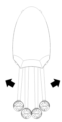
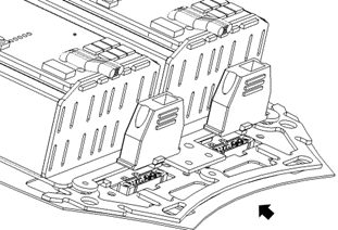
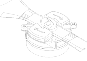
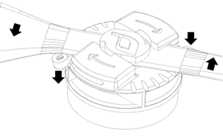
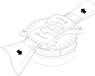
- Unfold the arms by pivoting them toward the nose of the airframe. They should snap firmly into place. Ensure the arms are fully seated in their clips
 |
 |
 |
|
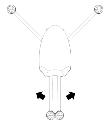
Rotate front arms into position. Arms should “snap” into place |
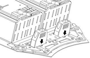
Rotate rears arms into postion. Arms should “snap” into place. |
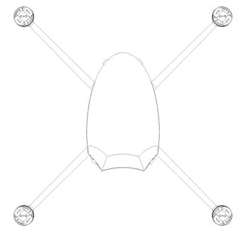
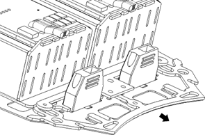
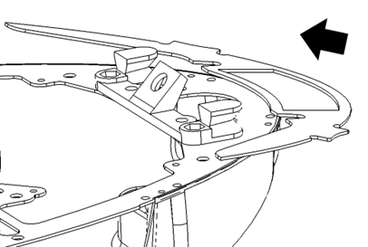
Arms correctly position. Note that diagonally opposed arms form a straight line. |
 |
 |
|
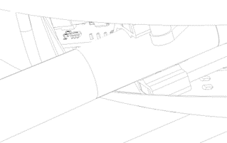
Front arm correctly “snapped” into place. |
Rear arm correctly “snapped’ into place. |
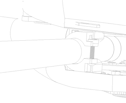
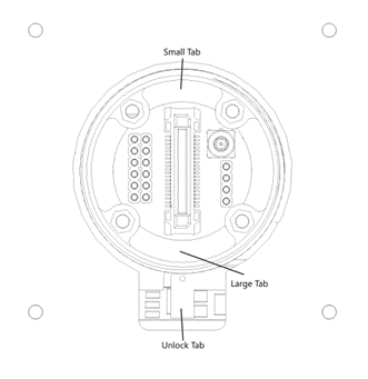
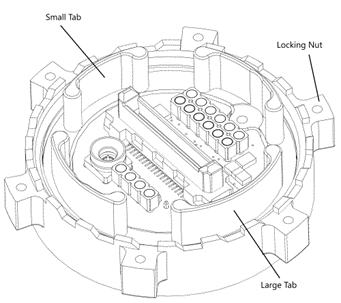
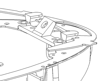
- Install the payload (if any). The payload interface has different sized “tabs” that engage with the airframe. Ensure these are correctly aligned. It may be necessary to wiggle the payload to get the connection to fully engage. Tighten the locking nut, there should be several “clicks” heard just before the nut is fully tightened.
 |
 |
|
Aircraft side payload connector. Note the location of the small and large tabs. Press the locking tab in to unlock the nut for removal. |
Payload side payload connector. Note the location of the small and large tabs. Use the locking nut to secure the payload. |
- Set the aircraft right side up on the landing gear.
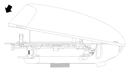
- Remove the canopy.
 |
|
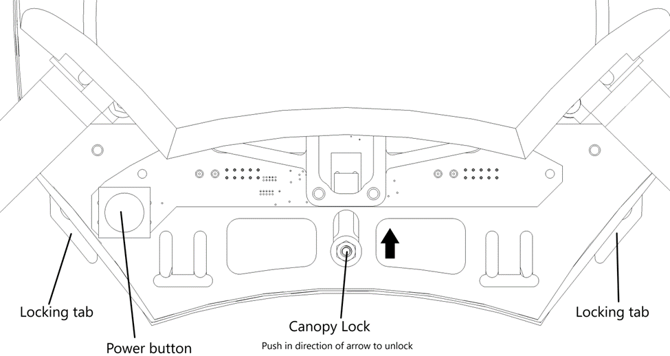
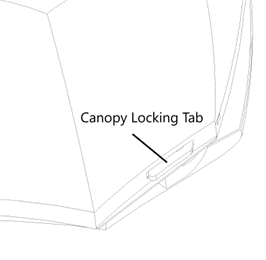
Underside view at rear of canopy. |
- Push the canopy lock forward until the locking tabs are clear of the canopy.
- Lift the rear end of the canopy up and forward
- Install flight batteries
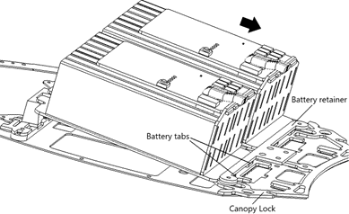
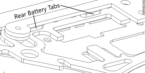
- Insert rear locking tabs of flight batteries between the battery retainer plate and the canopy slide lock.
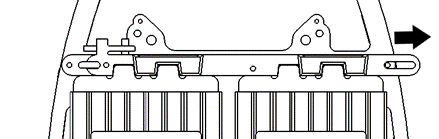
- Push the battery slide lock to the right side of the aircraft. This should allow the front locking tabs of the batteries to fall into place.
- Release the battery slide lock, it may be necessary to wiggle the batteries to allow the slide lock to return to its original position
 |
 |
|
Slide batteries in direction shown so that the tabs are on top of the canopy lock, and below the retainer plate. Notice that the batteries are at an angle relative to the deck plate. |
Detail view of battery tabs |
 |
 |
|
Slide battery lock in direction of arrow to allow batteries to drop into place. |
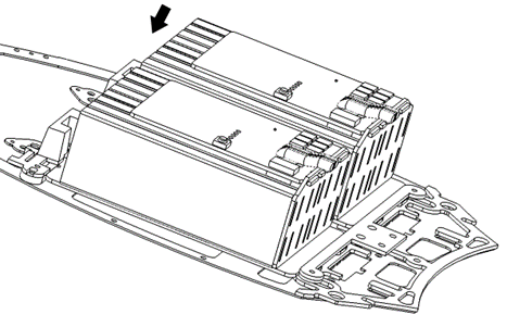
Batteries should drop into position. Allow battery lock to spring back into place. Batteries may need to be “wiggled” to get lock to return into position. |
- Push the canopy slide lock forward. Connect each battery to its corresponding connector on the airframe, ensuring the pins in the connector are aligned correctly (just note which side the big pins are on). Release the canopy slide lock. If it does not return to its original position the battery connects are likely not fully seated. This is usually fixed by wiggling the connectors gently while pushing down.
 |
 |
 |
|
Slide canopy lock forward |
Push battery connectors into place |
Allow canopy lock to return to locked position. |
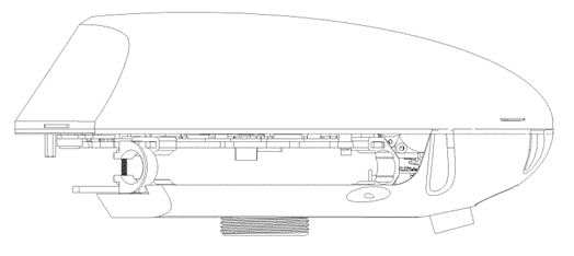
- Reinstall canopy.
- Hook front retainer plate onto matching hooks on the airframe
- Push canopy slide lock forward.
- Push rear end of canopy over the canopy slide lock
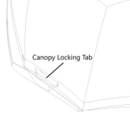
- Adjust position of rear of canopy until the locking tabs protrude fully through the canopy
- Grip canopy by the front “grips” and give it a firm pull upward to ensure it is properly seated. If there is more than 1mm of movement the canopy is not properly attached and may cause a crash.
 |
 |
|
1. Slide canopy on at an angle. It can be pressed against the edge of the lower canopy. (canopy hidden) |
2. Slide until the canopy has engaged the retainer on the airframe. (Canopy hidden) |
 |
 |
|
3. Canopy at angle before engaging on canopy lock |
4. Canopy in final position. Ensure locking tabs are protruding through the slots in the canopy by at least 3mm. |
 |
 |
 |
|
Canopy front grips, pull to ensure there is no movement when canopy is installed |
Left side canopy lock tab. Should be protruding at least 3mm through the matching slot in the canopy. |
Right side canopy lock tab. Should be protruding at least 3mm through the matching slot in the canopy. |
- Install the aircraft propellers
- Two clockwise and two counter-clockwise propellers are required
- Clockwise propellers go on the front left and back right arms
- Counter-clockwise propellers go on the front right and back left arms
- The propellers are keyed to prevent improper installation
- Align the motor shaft with the hole in the center of the propeller
- Set the propeller on the motor so that it is perpendicular to the final installed position
- Rotate the propeller opposite the direction of the arrows on the motor until it bumps into the locking pins
- Bend both locking pins down until the propeller can pass above them
- Rotate the propeller until it is fully seated in the mount, ensure the locking pins have snapped back up into place.
- Two clockwise and two counter-clockwise propellers are required
 |
  |
|
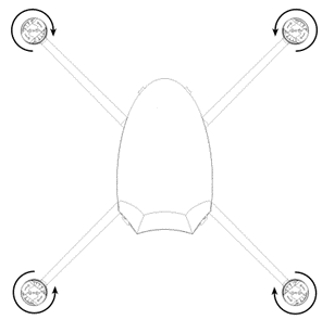
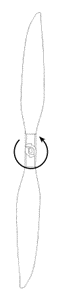
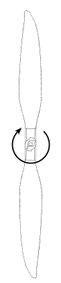
Propeller rotation direction for each arm |
Counter-clockwise and clockwise propellers |
 |
 |
 |
|
Clockwise propeller sitting in unlocked position |
Bend both tabs down while rotating propeller in the opposite direction |
Continue rotating in opposite direction until fully seated |
- Power on the aircraft by pressing the power button for approximately 1 second.
- Power on the RC controller by holding the power button for approximately 3 seconds